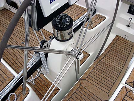
About transmission steering
When a direct link from the rudder to the pedestal via a rack and pinion system isn’t possible, the best, most direct and strong mechanical steering system to go for is the Jefa transmission steering system.
The transmission steering is based on the same principals as the rack and pinion system; the rotation of the wheel is transferred to a push pull movement via a gearbox and levers. The difference with the rack and pinion system is that the distance from the wheel to the rudder shaft can be much bigger and the routing more complex. Via torque tubes, universal joints, and bevel gearboxes, the rotating movement is transmitted to the reduction gearbox next to the rudder shaft. The reduction gearbox transfers the rotating movement into a push and pull movement on the tiller lever. As all rotating parts are running in roller bearings, and the system can be easily back driven by the rudder, the result is a steering system which can be far away from the rudder, but with the same precision and feel as a tiller steered boat.
The principle advantage of the transmission steering system over cable steering systems is the fact that the rudder torque is reduced by the reduction gearbox with a certain factor (between 5 and 23 depending on the chosen gearbox), so all further components are only loaded with a fraction of the real rudder loads.
Cable systems transmit the full rudder loadings to the steering shaft, so all components are loaded to the maximum rudder loads. Another advantage is the proportional reduction of the transmission steering compared to the linear reduction of cable systems.
The steering is very direct at midships and more indirect at full rudder. Due to this unique feature, the total number of turns of the wheel on a transmission steering system can be reduced with 30-40% compared to a cable system with the same maximum rim loads. Another big advantage of the rotating shaft work of the transmission steering is the easy integration of the autopilot drive unit. It can be integrated in the system on every bevel gearbox or on the reduction gearbox.
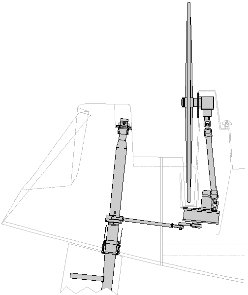
Example of a transmission steering system in a centre cockpit boat:
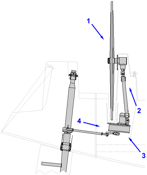
This layout shows the typical routing of the transmission steering in a centre cockpit boat. In this case the Contest 50CS build by the prestigious Dutch yard Conyplex. The TS300 pedestal is connected via 2 universal joints and a torque tube to the bevel gearbox mounted on the aft machine room bulkhead. At the front of this bevelbox the drive unit is integrated. At the other side of the bulkhead the system continuous under the aft cockpit floor into a self-aligning flange bearing and up underneath the owners bed into the reduction gearbox. The output lever of the reduction gearbox drives the draglink to the tiller lever.
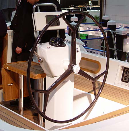
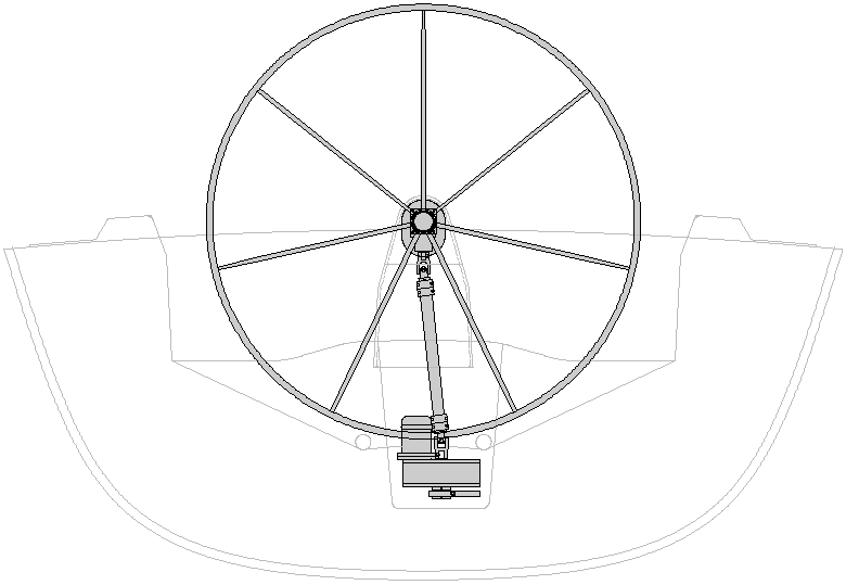
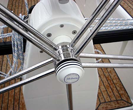
The cockpit with the TS300 pedestal with extended guardrail and instrument housing and the Jefa 1100 mm carbon wheel.

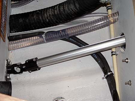
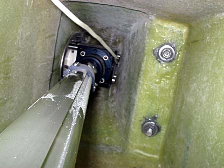
The cockpit floor underneath the pedestal. Via a universal joint the force is transmitted to the torque tube going down in the machine room.
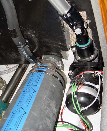
The bevel gearbox is mounted to the aft bulkhead. Please note the small dimensions of the drive unit which makes mounting on this position possible.
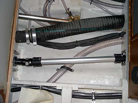
The bevel gearbox at the other side of the bulkhead driving the torque tube to the self-aligning flange bearing in the next bulkhead. This is normally the most difficult part of the routing as there is only a minimal vertical space.
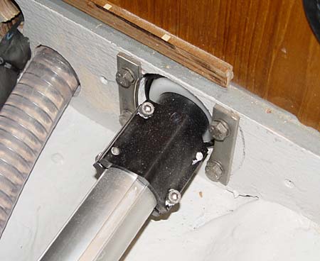
Detail view of the self-aligning flange bearing. The stainless counter plates are produced by the yard.
From the flange bearing, the routing goes up into the bevel reduction box. Please note that not every bulkhead crossing has to be done with a flange bearing.
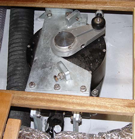
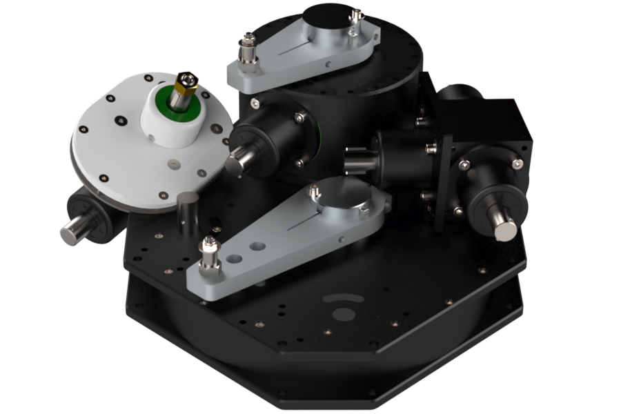
Top view of the BRG10-67 bevel reduction gearbox. Please note the custom adjustable travel limiter produced by the yard. This is not the rudder stop but a protection for the steering system.
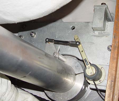
The tiller arm on the rudder stock. Over the tiller arm the plated rudder stop arrangement to protect the rudder and steering system and the autopilot rudder feedback unit.
Example of a transmission steering system in an aft cockpit boat:
This layout shows the typical routing of the transmission steering in an aft cockpit cruising/racing boat. In this case the X43 and X46 build by the prestigious Danish yard X-Yachts. The BG12QM steering gearbox is connected via 2 universal joints and a torque tube to the 3.2:1 input of the RG32-50 reduction gearbox mounted underneath the wheel trough. At the top of this reduction gearbox the drive unit is integrated using the 5:1 input. The output lever of the reduction gearbox drives the draglink to the tiller lever. Please look at the installation pictures in the photo gallery.
The cockpit with the pedestal integrated in the deck, the Jefa BG12QM "quick mount" steering box with a 1700 mm tandem steering wheel.
Close up of the pedestal with steering box.
The quick mount bevel box can be mounted from the outside so no extra inspection panels have to be made.
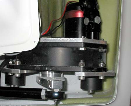
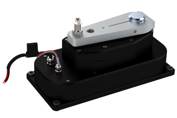
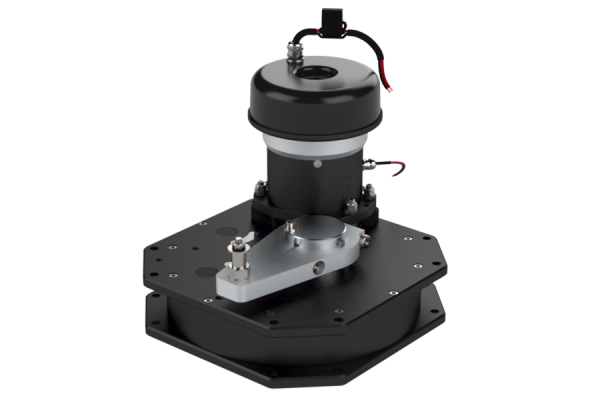
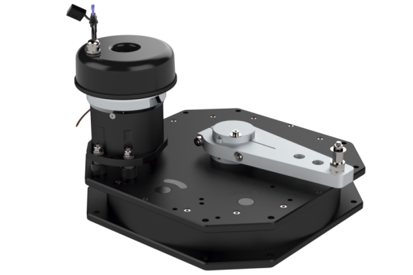
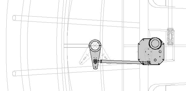
The RG32-50 reduction gearbox with integral stops and autopilot drive unit.
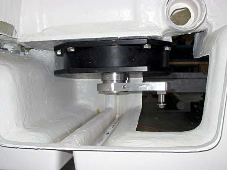
View from the rudder shaft to the reduction gearbox.
Wide Angle Geometry:
The lever geometry of the Jefa transmission systems is based on the principle of Wide Angle Geometry. This results in a very direct steering at midships (where the loads are low) and a more indirect and powerful steering at full rudder (where the loads are maximal). Due to this unique feature, the total number of turns of the wheel on a transmission steering system can be reduced with 30-40% compared to a cable system with the same maximum rim loads. This effect is achieved by an unequal length of the output and tiller lever. The output lever has 130 mm centres and the tiller lever 200 mm. The diagram below shows the mechanical advantage (lever reduction) in relation to the rudder angle. Around midships the reduction is quite constant, and at full over the mechanical advantage nearly doubles compared to the midships advantage. To setup wide angle geometry you set the levers perpendicular to the draglink while in midships position.
| Rudder Angle | mech. advantage |
| 0° | 1.54 |
| 5° | 1.54 |
| 10° | 1.56 |
| 15° | 1.60 |
| 20° | 1.67 |
| 25° | 1.78 |
| 30° | 1.99 |
| 36° | 2.50 |
Art. 11458